
Introduction of the transistor voltage stabilizing circuits
Voltage stability is a critical requirement in various electronic applications, where consistent and reliable power supplies are essential for proper device operation. The ability to maintain a stable voltage output is paramount in ensuring that sensitive electronics function as intended, without the risk of damage or malfunction. Transistor voltage stabilizing circuits have emerged as a dependable solution to this challenge. This passage delves into the intricate world of transistor voltage stabilizing circuits, uncovering their principles, components, and applications, while also exploring the advantages, design considerations, troubleshooting, and maintenance associated with these circuits.
Transistor Operation Fundamentals
A. Overview of the transistor operation
Before delving into the specifics of transistor voltage stabilizing circuits, it’s essential to understand the fundamentals of how transistors operate. Transistors are semiconductor devices that play a pivotal role in electronic circuits. They can amplify and switch electronic signals, and when configured appropriately, they become key components in voltage stabilization circuits.
Transistors operate based on the principles of semiconductor physics. They consist of three layers of semiconductor material: the emitter, base, and collector (in the case of bipolar junction transistors or BJTs), or the source, gate, and drain (in the case of field-effect transistors or FETs). By controlling the flow of current between these layers, transistors can regulate voltage.
Transistors can operate in three modes: cutoff, active, and saturation. In the cutoff mode, no current flows between the collector and emitter (or drain and source in FETs). In the active mode, the transistor is conducting, and it allows a controlled amount of current to flow. In the saturation mode, the transistor is fully conducting, and it allows the maximum possible current to flow.
B. Types of transistors commonly used in voltage stabilization circuits
There are two main types of transistors used in voltage stabilization circuits: bipolar junction transistors (BJTs) and field-effect transistors (FETs).
Bipolar Junction Transistors (BJTs):
BJTs have three layers of semiconductor material: the emitter, base, and collector.
They are commonly used in low- to moderate-power applications.
BJTs come in two types: NPN (N-type, P-type, N-type) and PNP (P-type, N-type, P-type).
NPN transistors have electrons as the majority of charge carriers, while PNP transistors have holes as the majority of charge carriers.
Field-Effect Transistors (FETs):
FETs have three terminals:
the source, gate, and drain.
They are commonly used in a wide range of applications, including voltage stabilization circuits.
FETs can be further categorized into MOSFETs (metal-oxide-Semiconductor FETs) and JFETs (junction FETs), each with its own characteristics and advantages.
Components and Circuitry
A. Description of key components in a transistor voltage stabilizing circuit
Transistor voltage-stabilizing circuits consist of various components that work together to regulate the output voltage. The key components include:
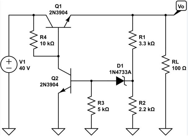
Transistors: These are the core components that control the flow of current. They act as the amplifiers and regulators, adjusting the current to maintain a stable output voltage.
Resistors: Resistors are used to set the operating conditions of the transistors and to provide biasing. They help control the current levels and protect the transistors.
Capacitors: Capacitors are often used for filtering and smoothing the output voltage. They reduce ripple and noise in the output.
Diodes: Diodes can be employed to protect against reverse voltage and prevent unwanted backflow of current.
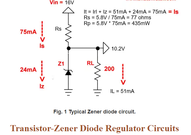
Voltage Reference: Voltage reference components, such as zener diodes, provide a stable reference voltage against which the output voltage is compared for regulation.
The arrangement and configuration of these components in the circuit play a crucial role in achieving the desired voltage stabilization.
Working Principle
A. How the transistor regulates voltage
Transistor voltage-stabilizing circuits operate on the principle of feedback control. These circuits maintain a constant output voltage by continuously comparing the actual output voltage with a reference voltage. When the output voltage deviates from the desired level, the circuit takes corrective action to bring it back within the specified range.
The feedback mechanism is typically based on negative feedback. Here’s how it works:
Reference Voltage: A stable reference voltage is set, often using a zener diode or another reference component. This reference voltage serves as a point of comparison.
Output Voltage Sensing: The actual output voltage is continuously monitored using a voltage divider or other sensing circuit.
Error Amplification: The voltage difference between the reference voltage and the output voltage, known as the error voltage, is amplified by an operational amplifier or other amplification components.
Control Action: The amplified error voltage controls the transistor’s operation. When the output voltage deviates from the reference voltage, the transistor adjusts its conductance to counteract the deviation and bring the output back to the desired level.
This feedback loop operates in real-time, making continuous adjustments to ensure that the output voltage remains stable, even in the presence of fluctuations in input voltage or changes in the connected load.
Advantages of Transistor Voltage Stabilization
A. Efficiency and reliability
Transistor voltage stabilizing circuits offer several advantages, making them a preferred choice in many applications:
Efficiency: These circuits are known for their efficiency in voltage regulation, as they only consume energy when needed for correction. This efficiency is particularly important in battery-powered devices or energy-conscious applications.
Reliability: Transistor-based voltage regulation is highly reliable. The feedback loop continuously monitors and adjusts the output voltage, ensuring that the voltage remains within the specified range, even in dynamic conditions.
Low Output Ripple: By using filtering components such as capacitors, transistor voltage stabilizing circuits can provide a low-ripple output, reducing noise and interference in sensitive electronic equipment.
B. Applications and use cases
Transistor voltage stabilizing circuits find applications in a wide range of industries and electronic devices:
Power Supplies: They are a fundamental component in linear and switching power supplies, ensuring that electronic devices receive stable and well-regulated power.
Audio Amplifiers: In audio equipment, voltage stability is crucial to prevent distortion and signal degradation. Transistor voltage stabilizing circuits are commonly used in audio amplifiers.
Communication Equipment: Telecommunications and data communication systems rely on stable voltage supplies to maintain network integrity and data transmission.
Power Management Systems: These circuits are used in power management systems to control the voltage supplied to various components within a larger system.
Lighting Systems: LED lighting systems often incorporate voltage regulation to ensure consistent brightness and longevity of the LEDs.
Automotive Electronics: Modern vehicles use voltage stabilizing circuits to regulate power for various onboard electronics, including entertainment systems, sensors, and control units.
The adaptability of transistor voltage-stabilizing circuits and their ability to maintain stable voltage levels in diverse applications highlight their importance in the electronics industry.
Design Considerations
When designing a transistor voltage-stabilizing circuit, several critical considerations must be taken into account to ensure its effectiveness and reliability:
Voltage and Current Requirements: Understand the specific voltage and current requirements of the application to select the appropriate transistors and components.
Load Characteristics: Analyze the load connected to the circuit, as different loads may require different voltage regulation characteristics.
Thermal Management: Transistors may generate heat during operation, particularly in high-power applications. Adequate heat dissipation measures, such as heat sinks or fans, are essential for maintaining transistor health.
Component Selection: Carefully choose the transistors, resistors, capacitors, and other components based on the requirements of the circuit. Component quality and tolerance are crucial for accurate regulation.
Input Voltage Range: Ensure that the circuit can handle variations in the input voltage without exceeding the component’s voltage ratings.
Stability and Bandwidth: Consider the circuit’s stability and bandwidth to ensure it responds appropriately to dynamic changes in the load or input voltage.
Troubleshooting and Maintenance
Transistor voltage-stabilizing circuits, like any electronic system, may encounter issues over time. Regular maintenance and troubleshooting can help ensure continued reliable operation.
Common Issues: Be aware of common issues such as component failure, incorrect biasing, and voltage reference problems.
Voltage Testing: Regularly test the output voltage to ensure it remains within the desired range. Any significant deviations may indicate a problem in the circuit.
Component Check: Inspect components for signs of damage or wear. Replace any faulty components promptly.
Calibration: If the circuit includes adjustable components, ensure they are correctly calibrated to maintain stable voltage regulation.
Cooling: Monitor the temperature of the transistors and ensure that any cooling measures, such as heat sinks, are functioning as expected.
Safety Precautions: When troubleshooting or maintaining the circuit, follow safety procedures and consider working with the circuit disconnected or de-energized to prevent electrical hazards.
Conclusion of the transistor voltage stabilizing circuits
In summary, transistor voltage stabilizing circuits are integral to modern electronics and power systems, ensuring that sensitive devices receive a stable and reliable power supply. By understanding the fundamentals of transistor operation, the components involved, the working principles, and the advantages they offer, one can appreciate their role in various industries. The design considerations for creating effective voltage regulation circuits and the importance of regular maintenance and troubleshooting practices are essential for ensuring their continued operation. As technology continues to advance, transistor voltage stabilizing circuits will remain a cornerstone of voltage regulation in the ever-expanding world of electronics.c