
I. Introduction
This article aims to provide an in-depth look at the concept, effects, and testing methods of dynamic on-state resistance. We will explore dynamic on-state resistance behavior in different types of power converters and provide some optimization strategies to improve power converter performance. In this study, we hope to provide engineers and researchers in the converter field with a deeper understanding of dynamic on-state resistance to improve power converter design and power performance.
II. Basic Principles of Power Converters
Here are the basic principles of power converters:
Input power supply: Power converters usually have an input power supply and an output power supply. The input power source can be AC power (usually from the grid) or DC power (such as batteries or solar cells).
Switching devices: Power converters usually use semiconductor devices, such as transistors (MOSFET, IGBT), diodes, etc., as switching devices. These switching devices can control the on and off of current to achieve the conversion of electrical energy.
Control circuit: Power converters require a control circuit to monitor input and output voltages, currents, and control the status of switching devices accordingly. This control circuit typically uses a microcontroller or other electronic components to perform these functions.
Pulse Width Modulation (PWM): Power converters often use pulse width modulation technology to control the operation of switching devices. PWM technology controls the amplitude and frequency of the output voltage or current by adjusting the on-off time of the switching device. This allows the power converter to convert electrical energy with high efficiency.
Inductors and Capacitors: Power converters often include inductive and capacitive components that are used to filter and stabilize the output voltage or current. These components help reduce current ripple and noise.
Output Power: The output power of a power converter provides the required voltage, current, or frequency to meet the requirements of a specific application.
III. Concept of dynamic on-state resistance
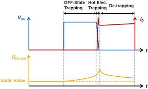
Dynamic On-Resistance means that when an electronic switching element (such as a metal oxide semiconductor field effect transistor, MOSFET) is in the on state, its resistance value changes dynamically with changes in time, current and voltage. Phenomenon. This phenomenon has important implications in high-frequency power converters and switching power supplies.
Typically, when MOSFETs or other switching elements are in the on state, they exhibit a resistance value, which is the static value of the on-state resistance. However, in high-frequency applications, the switching element switches multiple times in a short period of time, causing its resistance value to change as the current and voltage change during the switching process. This variation results in losses during the electrical energy conversion process because different resistance values cause heat dissipation during energy conversion.
The effects of dynamic on-state resistance can manifest themselves in power converter efficiency, voltage and current waveform distortion, and temperature rise. Therefore, understanding and managing dynamic on-state resistance is important to optimize power converter performance. Studying and testing dynamic on-state resistance can help engineers better design and select switching components to minimize energy loss, improve efficiency, and ensure stable operation of power converters in high-frequency and high-efficiency applications.
IV. Effect of dynamic on-state resistance on power converter performance
Dynamic on-state resistance has a significant impact on power converter performance, mainly reflected in the following aspects:
Reduced Efficiency: Dynamic on-state resistance causes the power converter to incur additional energy losses when switching elements switch, which reduces overall efficiency. This is especially important for high-efficiency power converters, as they are designed to minimize energy waste.
Increased heat dissipation: Additional energy losses result in increased heating of switching components, which may require a more powerful cooling system to keep the component’s operating temperature within an acceptable range. High temperatures can reduce equipment life and reduce system reliability.
Waveform distortion: Dynamic on-state resistance will affect the voltage and current waveforms output by the power converter, which may cause waveform distortion. This can have a negative impact on applications that require high-quality power waveforms, such as precision instruments and communications equipment.
Reduced overload capacity: The overload capacity of the power converter may be reduced due to additional energy losses. Under high load conditions, switching elements can become overloaded, compromising their performance and longevity.
Increased design complexity: To reduce problems caused by dynamic on-state resistance, more complex control strategies and switching element designs may be required. This increases the design and manufacturing costs of the power converter.
V. Testing and Measurement of Dynamic On-State Resistance
Dynamic on-state resistance testing and measurement is performed to understand the actual dynamic resistance characteristics of switching elements in power converters to better understand their performance. The following is a brief overview of testing and measurement of dynamic on-state resistance:
Test Method: Typically, testing of dynamic on-state resistance involves simulating the operating conditions of switching elements in power converters. This can be done by applying sine, square or pulse signals to simulate actual operating conditions. The test method should consider the application scenario of the power converter and the required test accuracy.
Test Equipment: Testing dynamic on-state resistance requires the use of special test equipment, such as high-frequency oscilloscopes, power electronic loads, and test fixtures. These devices can help record real-time changes in current, voltage, and resistance.
Test Circuit: During testing, a test circuit needs to be constructed in order to apply test signals to the switching elements and measure the relevant parameters. The design of the test circuit should consider the accuracy and safety of the test.
VI. Optimization strategy for dynamic on-state resistance
Optimizing the dynamic on-state resistance is to reduce the energy loss of the switching elements in the power converter and improve efficiency and performance. Here are some strategies for optimizing dynamic on-state resistance:
Select low on-state resistance components: Selecting switching components with lower on-state resistance is an effective strategy to reduce dynamic on-state resistance. Different types of transistors and power semiconductors have different on-state resistance values, so choosing the right components is crucial.
Reduce switching frequency: By reducing the switching frequency of the power converter, the additional energy losses caused by dynamic on-state resistance can be reduced. However, this requires a trade-off between switching frequency and power converter performance requirements.
Improved thermal design: An effective thermal system can reduce the temperature of switching components, thereby reducing the impact of dynamic on-state resistance. Good thermal design includes the selection and placement of heat sinks, fans, and thermal materials.
Adopt soft switching technology: Soft switching technology can reduce the rise and fall speed of current and voltage, and reduce the resistance change during switching. This helps reduce the effects of dynamic on-state resistance, but may require more complex control strategies.
Optimized control strategy: Improved control strategies can reduce the power consumption of switching elements during switching, thereby reducing the impact of dynamic on-state resistance. This includes the use of appropriate pulse width modulation techniques, feedback control and multi-stage topologies.