I. Introduction to 6N136 Optocoupler
A common optron, sometimes referred to as an optoisolator, that offers electrical isolation between the input and output circuits is the 6N136. It is made up of a photodetector and an infrared LED combined into one unit. By transferring signals through isolation barriers, this part keeps interference out of sensitive circuits and lowers noise levels.
II. Basic Operation and Components
A. Explanation of Optocoupler Functionality
The concept of optical coupling underpins the operation of optronics, including the 6N136. The optron’s LED (light emitting diode) component emits light in response to an input signal. An output signal is produced when a photodetector component, usually a phototransistor or photodiode, detects this light. Crucially, the input and output are electrically isolated from one another to guarantee that signals are sent through a direct electrical connection.
B. Components Involved in 6N136
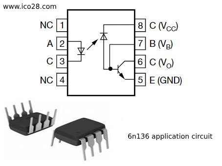
The 6N136 optron is made up of several important parts that are combined into one unit. These include a photodetector, which transforms incoming light into an electrical signal, and an infrared LED, which emits light when tilted. Input and output pins are also present for attaching external circuitry. There might also be internal resistors or capacitors in the package to safeguard or condition the signal.
III. Typical Application Circuits
A. Isolation and Signal Transmission
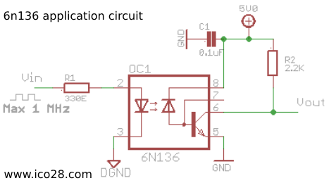
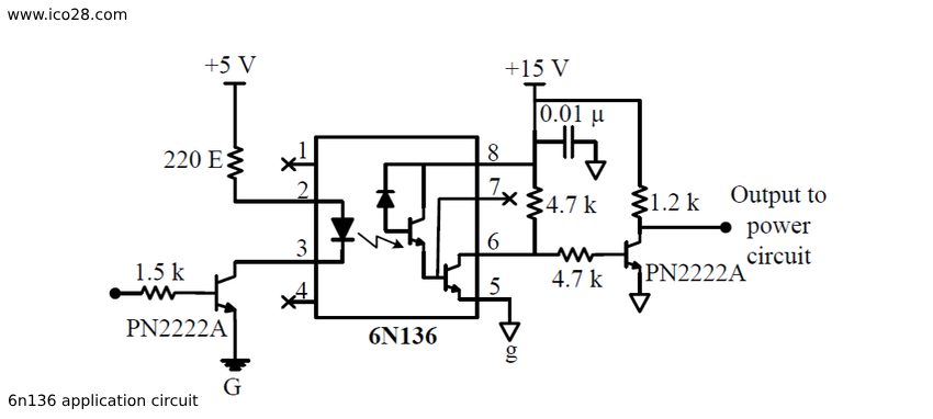
Signal transmission isolation circuits are a typical use for the 6N136 optron. In these circuits, signal transmission is permitted while electrical isolation is provided by the optron’s electrical isolation between the two circuits. This is especially helpful in situations when it’s important to shield delicate components from interference from noise or high voltage. Examples include protecting low-voltage sensors in industrial settings, isolating communication lines in data communication systems, and isolating microcontrollers from high-power circuits.
B. Voltage Regulation and Control
The 6N136 is likewise applicable in these types of circuits. By modifying the output voltage in response to the input voltage or reference voltage, feedback loops enable the optron to control the voltage. This is frequently observed in switching mode power supply, where feedback circuits utilizing optrons are employed to control and stabilize the output voltage. Moreover, power regulation applications like motor speed control and LED light dimming can benefit from the use of optrons.
C. Motor Drive and Power Management
The 6N136 is essential for regulating the power supply to motors and other high-power devices in motor drive and power management applications. The optocoupler guarantees safe operation by separating the control circuitry from the high-power components and shields delicate electronics from voltage spikes or disruptions. Motor driving circuits used in robotics, automotive, and industrial machinery applications frequently exhibit this. In addition, complicated systems like renewable energy or uninterruptible power supply (UPS) can use the 6N136 in power management systems to monitor and regulate the distribution of electrical power.
IV. Performance Considerations and Design Tips
A. Signal Integrity and Noise Immunity
When designing optron 6N136 circuits, it is essential to guarantee both signal integrity and noise immunity. Maintaining signal integrity and reducing electromagnetic interference (EMI) requires careful planning and application of shielding techniques. To lessen signal distortion and attenuate noise, care should also be taken in choosing the right filtering components.
B. Component Selection and Configuration
The effectiveness of 6N136-based designs is greatly dependent on the choice of components and the configuration of circuit parameters. It is crucial to choose components with the right specifications, such as those that align the optron’s input and output properties with the demands of the application. Furthermore, circuit stability and efficiency can be raised by setting up components like bias resistors and feedback loops in accordance with manufacturer guidelines.
C. Thermal Management and Efficiency
Especially in high power applications, thermal control plays a vital role in preserving the Optron 6N136 circuits’ dependability and efficiency. To keep the optron from overheating and to guarantee long-term stability, appropriate heat absorption and dissipation methods must be applied. Optimizing operating parameters like voltage and current can also aid in lowering power losses and increasing circuit efficiency.
V. Troubleshooting and Common Issues
A. Diagnosis of Circuit Failures
Investigation and diagnosis of potential issues are necessary for troubleshooting circuit faults connected to 6N136 optronics. Signal distortion, erratic behavior, or total circuit failure are examples of common issues. In order to ensure correct wiring and component placement, engineers should begin by inspecting the circuit connections. Subsequently, evaluating specific parts, including LEDs and photodetectors, can aid in locating problematic components. Anomalies can also be found by using oscilloscopes or signal analyzers to check waveform properties and signal integrity.
B. Mitigation Strategies for Performance Issues
Engineers can employ a range of tactics to enhance overall functionality when exposed to circuits using the 6N136 optron beam. For instance, adding filtering elements like capacitors or ferrite beads can reduce unwanted noise and enhance signal quality if signal distortion or noise interference is noticed. Similarly, the operational parameters of the circuit can be optimized to increase stability and efficiency by modifying feedback networks or slope resistors. Furthermore, maintaining appropriate thermal management—that is, sufficient ventilation or heat absorption—can reduce overheating and enhance long-term dependability.
VI. Real-world Applications and Case Studies
A. Examples from Industrial Automation
The optron 6N136 is widely used in industrial automation for many different applications that need signal transmission and electrical isolation. To ensure safety and dependability, it is frequently utilized in motor control circuits, for instance, where it isolates the microcontroller and high power motor drivers. Furthermore, the 6N136 enhances system integrity and performance in PLC (programmable logic controller) systems by facilitating communication between various modules while preserving electrical isolation.
B. Implementations in Consumer Electronics
Consumer electronics benefit from the 6N136 optocoupler’s ability to provide isolation and signal transmission in compact and efficient designs. In audio equipment, such as amplifiers and mixers, it isolates sensitive circuitry from high-voltage components, reducing noise and improving audio quality. Similarly, in power supplies and battery chargers, the 6N136 enables feedback control and voltage regulation while ensuring electrical safety. Its integration into consumer electronics demonstrates its versatility and reliability in demanding applications, contributing to enhanced performance and user experience.
C. Usage in Automotive Systems
The 6N136 optron is used in automotive systems for a number of purposes, including as safety, control, and communication. To ensure precise and dependable functioning, it is utilized, for instance, in engine control modules (ECM) to isolate sensors and actuators from the high-voltage systems of the car. Furthermore, the 6N136 offers electrical isolation for enhanced safety and makes dimming control and fault detection in lighting systems easier.

VII. Conclusion
In conclusion, engineers and designers who want to create effective, dependable, and secure electronic systems must have a solid understanding of the 6N136 application circuits. Engineers may solve the difficulties of contemporary circuit design and progress technology across a range of industries by skillfully utilizing the capabilities of the 6N136 and other optronics.